Welcome to Sino Bearings web
24x7 HOTLINE:+86-28-81454188

 NEWS
NEWS
Markus Raabe discusses the issues that influence shaft and bearing stiffness
People often ask about stiffness values of bearings or shafts and it is not really clear what information they actually need. The stiffness can be used for the calculation of critical speeds or natural frequencies or for the assessment of machine tools, which should only show little deformations under load.
Bearing catalogues sometimes provide values for axial and radial stiffness, but these are only values for one load direction without any information on the mounting state and without cross coupling between axial and radial deformation. If diagrams are shown the stiffness rises with the load.
Fig. 1 shows the radial stiffness of a 7210 angular contact ball bearing with axial preload of 500N under increasing radial load. Does the stiffness increase with load? Why are there three curves and not only one?
What is the bearing stiffness?
To calculate stiffness, frequently force over deflection is used, but this is only correct for linear and for one-dimensional systems. More accurately the variation of force over variation of deflection ∆F/∆u (Difference quotient) or ∂F/∂u (partial derivative) should be used. The result for a bearing with five position parameters (three displacements and two angles) and F(ux, uy, uz, ry, rz) a 5x5 stiffness matrix is shown in Table 1.
The compliance is the variation of deflection over variation of force ∆u/∆F (Difference quotient) or ∂u/∂F (partial derivative) and for a bearing with u(Fx, Fy, Fz, My, Mz) a 5x5 compliance matrix can be derived, as shown in Table 2.
Note that for the main diagonal in y-direction for example, the stiffness value of 232.54 N/µm is very different from the inverse of the compliance value 1/0.081688=12.2 N/µm. The first value is the radial force variation over radial displacement for constant displacements ux, uz and rotations ry, rz while the second ratio is for constant forces Fx, Fz and constant moments My, Mz.
The three curves in Fig. 1 are generated using cyy=∂F (ux, uy, uz, ry, rz)/ ∂uy; cyy2=1/(∂uy(Fx, Fy, Fz, My, Mz)/ ∂Fy) ; cyy3=1/(∂uy(Fx, Fy, Fz)/ ∂Fy). So, the first curve is the main diagonal of a 5x5-stiffness matrix, the second curve is the reciprocal value of the main diagonal of the 5x5 compliance matrix and the third value is the reciprocal of the main diagonal of the 3x3 compliance matrix for a bearing with fixed tilting angle. All curves show a ratio of force difference over deflection difference. Just the conditions for other parameters are different, having either fixed displacements or fixed forces.
Why is the bearing stiffness reduced under increased radial force?
This is because of constant axial force, like with spring pretension and the load distribution changes. For pure axial load all rolling elements have the same load. With rising radial load some rolling elements are unloaded, and this leads to the initial decrease of radial stiffness.
For the spindle in Fig. 2 a radial and axial stiffness for the left end should be calculated. A measurement would probably be done by applying a force and measuring the deflection. This would relate to the main diagonal element of a reduced compliance matrix as other deflections and tilting angles are not restricted. The main diagonal element of the stiffness matrix would show much larger values.
The catalogue stiffness for bearings is only taking into account geometry and manufactured pretension. The stiffness is then affected by mounting conditions such as interference fits, or operating conditions such as rotation speed and temperatures. If there is clearance between the outer ring and the housing, the outer ring can expand radially, which will decrease the stiffness. Fig. 2 shows the influence on bearing and spindle stiffness as an example. In case of the temperature difference the spindle stiffness decreases because the axial expansion of the shaft leads to a reduced bearing pretension.
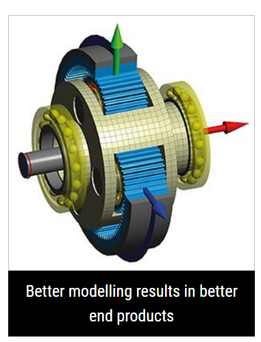
Elastic deformations of the housing or other elastic surroundings will also have an influence on the stiffness of shaft-bearing systems. A calculation model for housing stiffness is just more difficult. Often FEA models of housings are statically reduced to consider their stiffness. Fig. 3 shows four modelling approaches for the reduction of housing stiffness. The first is a reduction to a central node using rigid constraints. This will stiffen the housing. The second approach is a reduction to a central node using averaging. Then the housing is not stiffened, but the displacements will not match. The third approach couples the housing deformations with deformations of the bearing ring. Note that there is a vertical movement in the example because of the deformed shape. The fourth adds a contact model between housing and bearing ring. Increased model complexity increases accuracy but also calculation time.